Univesal Joint Phasing
The Concept and Importance of Universal Joint Phasing and Drive Shaft Alignment
Phasing is the process of aligning the universal joint yokes on both ends of the drive shaft (or double u-joint)in a parallel fashion. If the joints are not properly phased, they will operate at varying speeds throughout each revolution which can cause second-order vibrations. The vibration can lead to increased wear and potential damage to the assembly and failure of the application.
Belden’s trained technicians properly phase the universal joints onto the shaft during assembly, ensuring that the inbound vs outbound shaft of the universal joint assembly operate at near-constant velocity, minimizing vibration, noise and premature wear of the joints.
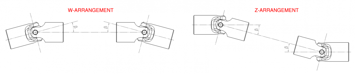
To further support near-constant velocity, driving and driven shafts are required to be aligned in either the “W” formation (equal true angles) or “Z” formation (parallel). It is important that the drive shaft is not angled further in a '3rd dimension'. ” In addition to diminished velocity and reduced efficiency, improper shaft alignment contributes to failure of the shaft components and even the application itself.
A word of caution: even though driving and driven shafts are now at constant velocity, this is not true for the center section – that still fluctuates which can cause problems at elevated speeds of @ 4000 RPM.
Please reach out to our technical sales and engineers to answer any questions and assist you with the alignment and phasing of your universal joints.
Connecting Multiple U-Joints
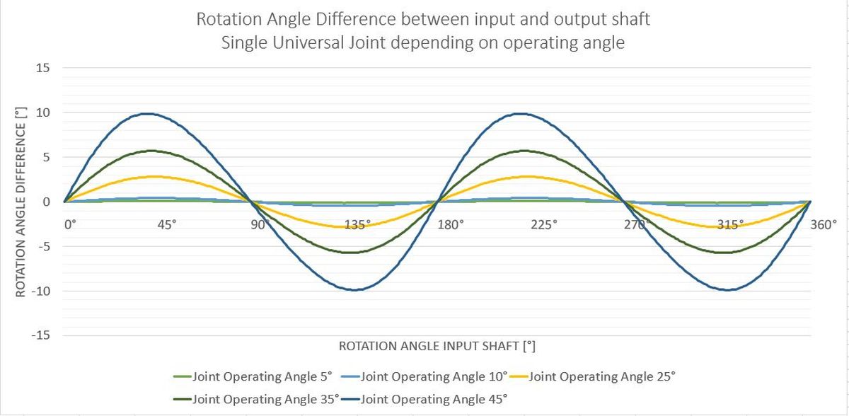
The major advantage of selecting universal joints instead of other types of couplings is their ability to compensate for greater angular misalignments while transmitting relatively high torques.
Single U-Joints can compensate for an angular misalignment of up to 45 degrees between the input and output shaft. In some very specific cases, this angle can be increased even further, but this is not recommended for use with any significant rotational speed.
The angle can also be increased by attaching multiple universal joints in line. However, each additional joint requires a support to limit the degrees of freedom and ensure the proper transmission of torque and motion. Additional U Joints and supports add friction and thus reduce the efficiency of the power transmission chain.
Typically, the connection of 2 single Joints is the most common variant of sequenced joints. A user can either connect two single joints by pinning or welding the hubs together or use a single center component, also called a ‘double yoke’, eliminating the need for additional machining, welding, and assembling.
Depending on size and type of Joint, these center components are available as part of the standard product range or are made to order. For some less popular sizes, manufacturers revert to the connection of 2 single U Joints with the aforementioned methods.
Double universal joints cannot only increase the operating angle going around a corner (sometimes referred to as "W configuration"), they also allow for the compensation of parallel misalignment between driving and driven shaft (a “Z configuration”).

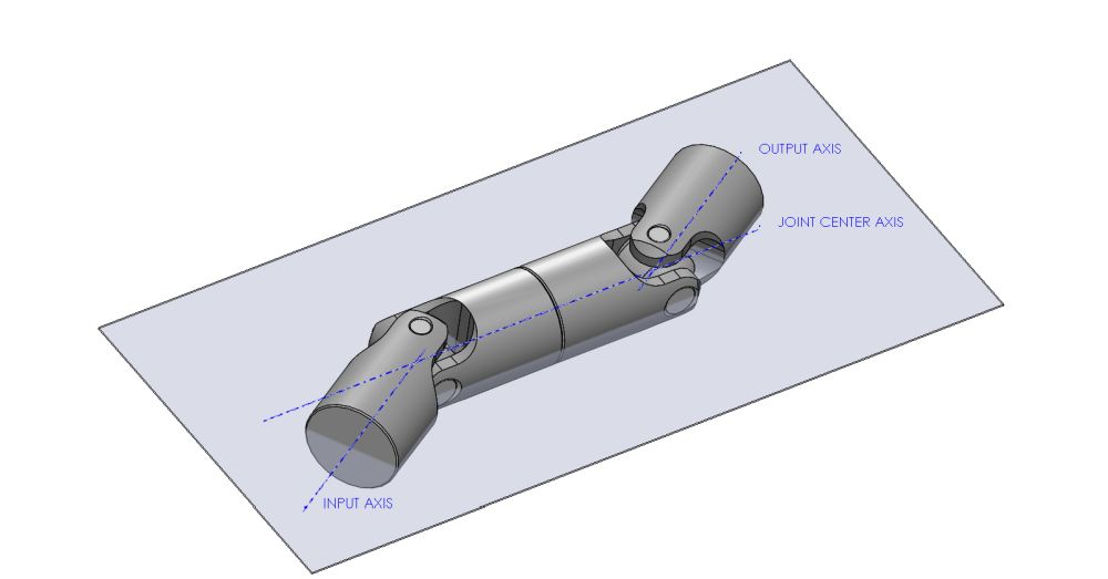
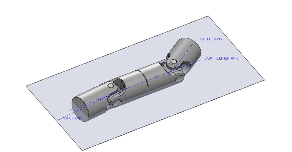
U-Joints in incorrect W and Z configuration on a virtual plane
Both configurations offer nearly constant velocity between the ingoing and outgoing end of the joint.
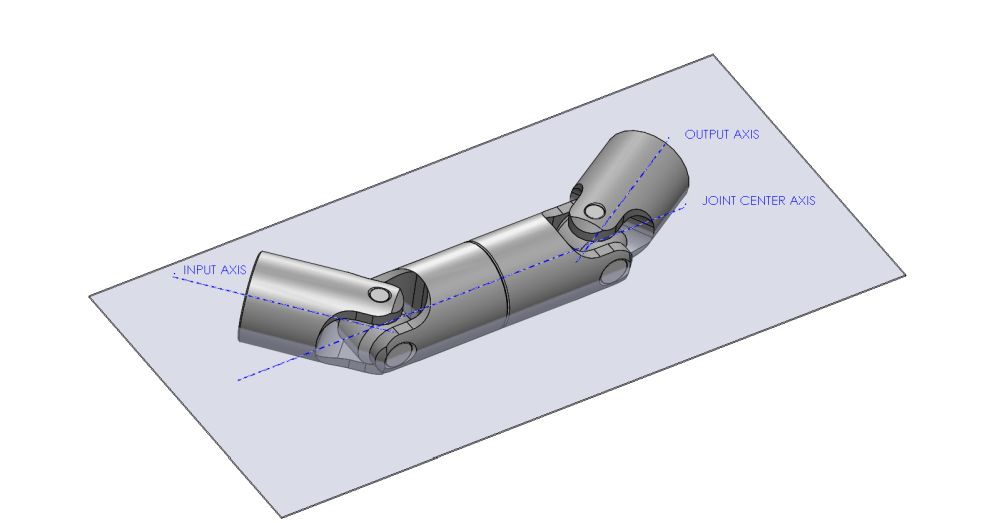
However, a few conditions must be met. The double joint must be located on a virtual plane and the operating angles of the two joints must be the same. If one or both joint ends are placed at an angle that takes the assembly from the virtual plane into a free 3D configuration, the constant velocity relation is lost. Also, the two joints need to be phased at 180° against each other, aligning the inwards pointing yokes.
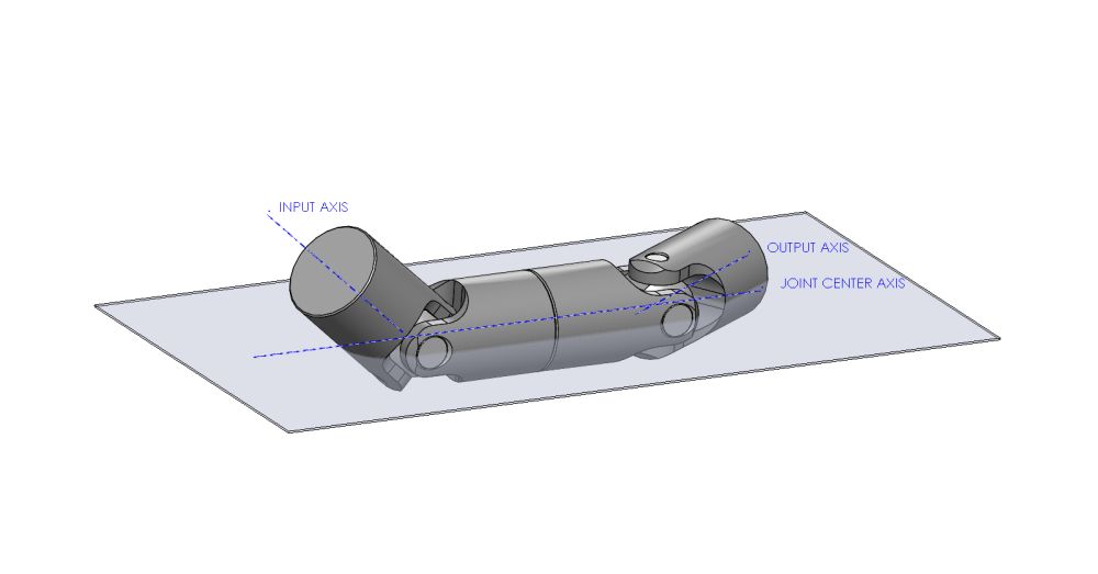
U-Joints not on a virtual plane
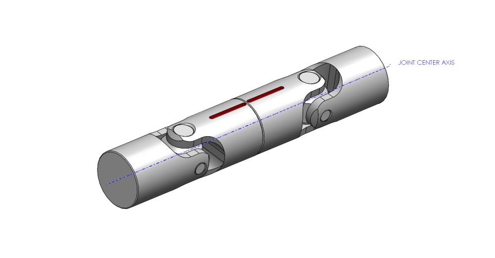
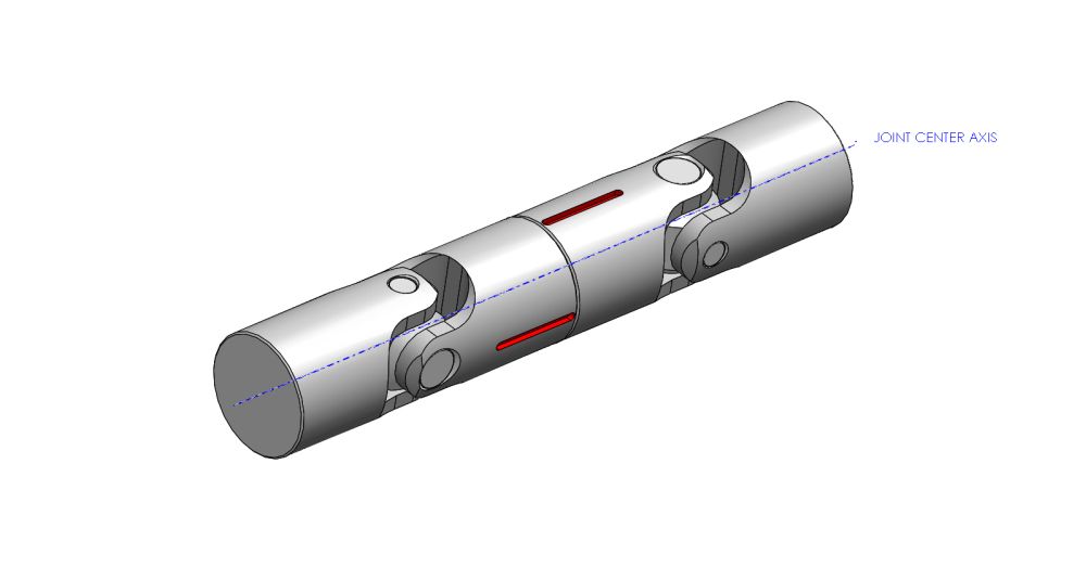
U-Joints with correct and incorrect phasing